 |
|
|
|---|---|---|
| |
|
|
Production Process Of A High Temperature Mold And Propeller
This outline is written from my personal experience from making molds and carbon propellers. There are many variations of resins and processes but the basics normally remain the same. The type of resins used for propeller making and mold making will remain proprietary. This outline will not deal with aerodynamics or formulas since this would take more information and equipment than I have at my disposal. This page is somewhat under development and the pictures that go with the text will be included as the propeller and mold are fabricated.
All epoxies if allowed to come in contact with the skin accumulate in the body or have an accumulative effect. The effect might not show up for months or years until they have built up enough to cause an allergic reaction. Therefore it is mandatory that the proper eye and skin protection be worn when working with epoxy resins. Contact with glass or carbon fibers are annoying in the least. Breathing the carbon or fiberglass dust is also harmful. Personal protective equipment based on the information included in the chemical suppliers MSDS (Material Safety Data Sheet). If there is sanding of carbon or fiberglass a downdraft table with a dust mask is recommended. A downdraft table does what the name implies; it pulls the air downward into the table through a filter system. Never clean epoxy from the skin with acetone. The acetone will dissolve the epoxy and send it deep into the pores of the skin creating greater exposure. The acetone also has a drying effect on the skin creating further health hazards. If epoxy comes in contact with the skin refer to the MSDS for proper removal. Soap and water is usually the recommendation for cleaning epoxy from the skin. Industrial epoxies require more stringent safety measures than the variety found in the hobby shops.
In recent years epoxy has become a household word. Epoxy is a general term used to describe a vast number of specialized resin/hardener systems, just as "aluminum" is a general term for a whole family of specialized metal alloys. The aluminum in a spar of a high performance aircraft is vastly different from the aluminum pots and pans in your kitchen, the epoxy used to create structural parts are vastly different than the variety found in the hobby shops. Since you are the material manufacturer, it is necessary that the proportioning and mixing operation follow the resin manufacturers specifications, or the material will be weak. Mixing epoxy in small quantities by weight require a triple beam gram scale for accuracy. A gram scale of this type will weigh in increments of one tenth of a gram. Electronic scales in general are not accurate enough when mixing small quantities since they tend to round to the nearest half gram or whole gram. There are three methods to obtain the proper ratio of hardener and epoxy: Proportion by weight, proportion by volume, and proportion by means of a special pump. Of these three the most accurate method is mixing by weight. The triple beam gram scale that I use doesn't have a tare weight dial, so the weight of the cup needs to be subtracted from the resin before figuring the correct ratio of hardener. The resin is always referred to as "100%". The hardener (also called catalyst) is given in percent of the resin weight phr (parts per hundred weight). Sometimes this is referred to as PBW (parts by weight).
Carbon fiber model airplane propellers are usually developed over a lengthy trial and error method. Since no propeller is the best propeller under all conditions it is beneficial to have a variety of sizes and pitches available. I feel the two things that will most affect the performance of a control line aerobatic airplane after it has been trimmed out and straight is the engine propeller combination. With the excellent engines that are being produced for control line stunt half the battle has been won. Once the engine is running in the rpm range it was designed and set up for then it is up to the propeller to control the speed of the airplane through its pitch. Pitch on a C/L aerobatic model airplane propeller is measured in fractions of inches, usually in one tenth of an inch. The pitch of a model airplane propeller is adjusted according to the RPM (revolutions per minute) the engine is turning. Through the varying of the pitch of the propeller the ideal lap times can be achieved. The higher the RPM the less pitch you need for a given speed. The efficiency of a propeller blade is another factor contributing to the performance. Gyroscopic procession is also a consideration in control line aerobatics. The larger the propeller diameter the less cornering ability the plane will have due to the propeller acting as a gyroscope. I have also noticed two verses three blade propellers affect the cornering of an airplane. Without going into detail it becomes obvious that the design of a competitive model airplane propeller tends to evolve over trial and error. If one doesn't have the desire or time to make their own propellers it is advantageous to understand how to rework a carbon prop either by reducing the diameter, thinning the blade, adding of subtracting pitch, or balancing. The widening or lengthening of a carbon blade should only be attempted when making a master plug for a mold, and should never be used on an engine. The reasoning behind not lengthening or widening a carbon blade for other than static or mold making is due to the fact that when carbon tow is spliced onto an existing blade it is not structurally sound enough to take the load of an engine. The carbon fiber prop is strong due to the continuous length of tow in the lay-up. If this continuous length is disturbed or broken then a stress riser is created, which is the area where failure will most likely occur. The way the carbon roving is layered or (scheduled) into the mold is also important. As far as damaged carbon props are concerned it is better to discard the blade than risk injury to yourself or others by using a damaged or unsafe propeller on an airplane. The propeller chosen for this project is one that would perform better if there were approximately 1/8 inch more chord on the blade from the tip tapering to the middle of the blade. After examining the blade there were voids around the hub area that needed to be filled. The propeller had an shattered tip that also needed to be extended for more diameter. The hub of this blade could also be thinned from top to bottom by approximately 3/16 of an inch. The only thing this prop was good for at this point due to the damage sustained was a mockup for mold construction. This paper will discuss the process that is necessary to achieve a new prop blade of altered dimensions that is air worthy. The first step is to remove all loose carbon strands from the damaged tip and open up the voids in the hub area. Once the prop is cleaned of all loose strands a thorough cleaning of the surface with acetone will remove oils or contaminants and allow the epoxy to adhere to the surface. A rough sanding where there will be secondary bonding would also be a good idea. Remember the epoxy only has to stick well enough to construct a plug. WARNING the prop at this point or any time in the future cannot be considered a structural part. To widen the blade the specified 1/8 inch, glue .010 or thicker Mylar to the bottom of the blade with cyanoacrylate glue with about 1/4 inch overhang around the perimeter of the blade. Waxing the Mylar first will still allow the CA glue to stick but will aid removal from the epoxy later. If the Mylar is too thick it will not conform to the bottom of the blade, especially if there is under camber. The Mylar will support the carbon roving and maintain the approximate pitch of the blade. The Mylar is used to create a dam for the carbon roving to lie against. The Mylar only has to extend to about 1/4 inch past where the blade will be widened. Don't run the Mylar all the way to the hub since the blade will not be widened in this area.
The picture above shows the see-temp applied to the back of the blade ready for the carbon tow to be added. Wet out approximately ten strands of carbon tow 4 inches long and lay them along the trailing edge of the blade. Refer to Mixing Epoxy for the proper procedure on mixing. A 50-50 ratio of resin to carbon by volume is sufficient for wet out. Plastic gloves are a must here since the epoxy and curing agent are a strong skin sensitizer. The use of a 3/8 inch acid brush aids in the transfer of resin from the cup to the carbon tow. If the carbon becomes resin rich, blot away the excess resin with paper towels. They should overlap the top of the blade approximately 1/8 inch and extend out past the trailing edge of the blade 3/16 inch. The Mylar or See-Temp will support the tow from the bottom of the blade. If the diameter of the blade is going to be increased at this time add the carbon tow at the tip of the blade with the fibers running the span of the blade. It is better to add too much tow at this point since the excess can be sanded away to the desired shape latter. Set aside upright to cure. The ideal temperature is 77 deg to 95 deg Fahrenheit for most room temperature resins. Once the resin has cured 24 to 36 hours remove the Mylar or See-Temp from the back of the blade.
The next step is to make a template out of See-Temp or Mylar for the top outline of the blade. This template will be rotated around a drill rod installed in the hub of the blade. The template should be the desired top view of the propeller blade. Since the template is an outline of the top view of the blade you want to reproduce, you are assured a mirror image of each blade by rotating the template about the drill rod and tracing it onto each blade. Scribe a line on top of the blade that bisects the shaft hole on the blade and continues out to the center of each tip. On your template mark the center of the tip. This is where the opacity of the Mylar or See-Temp becomes an advantage. You are able to align the centerlines of the prop tips to the template because you can see through the template material. When rotating the template around the droll rod the marks on the template are reference marks to align the template. The idea is to keep each blade at 180 degrees to each other. Trim the blade to match the template. Small sanding drums on a Dremel tool work well as long as the rpm is held down to approximately 5,000 to 10,000 rpm's. Hand files also work well for this purpose. A dust mask is a must in this operation along with proper ventilation, preferably a down draft table. At this time sand any pinholes or any bubbles you have filled. At the hub of the blade make sure you have a draft angle of about 1 to 3 degrees. The top of the blade at the hub should taper out to a larger diameter at the base of the hub. This angle will allow the prop to release from the mold. The modeling clay will create the other draft angles covered in Claying Up The Master Plug. Once the top view or outline shape of the blade is established it is time to set the tracking of the tips and the pitch of the blade. The pitch and tracking are dependent on how true the back side of the hub is machined. Set the blade on a tooling plate and rotate the blade tips past the height gage to see if each blade is tracking on the same plane. If the tip of one blade is higher than the other, the hub can be sanded to allow the blade to track. Remove material from the side of the hub that is high. Remember you are removing material from the hub that rests against the thrust washer of the engine. If you modify the blade in this manner you might have to enlarge the drive shaft hole in the blade slightly to assure the drill rod is at right angles to the base of the blade. Don’t worry about slightly enlarging the hole since any gaps will be filled with clay when making the plug mock up. The important thing is that the drill rod is at right angles to the backside of the hub and the blade tips are tracking on the same plane.
The best base material for creating the blade mock up is ¼ inch aluminum. Softer materials will scratch and cut when the modeling clay is cut away from the blade therefore aluminum seems to be the best material. Cut a piece of aluminum to accommodate the size of propeller you are making. For the propeller in this report the aluminum sheet is 4 inches x 14 inches. It is better to have the plate a little oversize than too small. Drill a hole 5/16 in this case in the center of the aluminum plate. 5/16 is the drive shaft dia. of the engine that this prop will be used on. The center of the aluminum plate can be located by connecting the four corners with a straight line, where they intersect in the middle of the plate is where the center is. Drill the 5/16 hole here. Center punching the mark where you are going to drill the hole will help keep the drill bit from wandering. Use a drill press with the table set up at right angles to the drill bit. This will insure that the drill rod will be at right angles to the base of the blade. If the drill rod is not at right angles to the base of the blade or aluminum plate, then the hole going through the blade will not be at right angles to the back of the blade hub. Binding will occur when trying to install the blade on the engine. The shaft hole in the aluminum plate can be drilled larger than the drill rod. Tack gluing a wooden block o the underside of the aluminum plate will allow changing to different drill rod sizes. The wooden block is drilled to the correct diameter to stabilize the drill rod. Once the drill rod is in place check to make sure that it is square to the aluminum plate. Take the finished mock-up blade and place it on the aluminum plate with the drill rod positioned in the plate. The drill rod should be approx 6 inches in length since it will be used on the finished mold. The drill rod should extend through the aluminum plate and through the propeller. At the top ½ inch of the drill rod there needs to be a 1/8 through hole with a chamfer around both sides of the hole. The hole is there to accept a 1/8-inch piece of music wire to create a handle to remove the drill rod from the mold when making the prop. After drilling and chamfering the hole in the drill rod heat the last inch with a torch until cherry red and quench in cold water or oil depending on the type of drill rod. This will harden the metal surrounding the hole. The music wire running through the drill rod creates a T handle and allows a twisting and pulling motion to facilitate the removal of the drill rod from the center of the mold. The hole needs to be chamfered to keep any burs from damaging the top half of the mold when it is being slid over the drill rod prior to mold clamping. It is important to use drill rod to insure that the rod will release from the resin. The drill rod is center less ground to close tolerances to create a smooth surface without any undercuts that would lock it into the resin. The use of any other rod material will cause it to errantly lock itself into the resin Up till now you should have a blade with symmetry, equal top view areas and the length of each blade should be identical. The top and bottom of the hub should also be at right angles to the shaft hole. The next step is to set the pitch of the blade. Remember how the hub could affect the tracking of the tip of the blades? The same holds true to the pitch of the blade. If the blade pitch needs to be 3.8 inches from the hub to the tip and one blade is 4.0 inches and the other is 3.6 inches then the problem can be corrected at the hub by sanding material off of the backside of the hub on the high side enough to get the blade to rock to the side to provide equal pitch of both blades. This only holds true on the mock up since doing this would put the shaft of the engine in a bind when tightening the prop nut. After doing this, the face of the hub should be trued up to right angles to the shaft or drill rod. A perfect composite propeller directly from the mold is hard to obtain. Therefore it is usually accepted that the blade has to be fine tuned before it can be used. If the pitch is only off on one blade then the best method is to sand in the pitch with 120 grit sand paper finishing with 320-grit or finer. Use the pitch gage to check frequently so as not to take away too much material. The best pitch gage for this size of propeller is the Prather Pitch Gage. On this project propeller, pitch should be a constant 3.8 inches. By constant I am referring to the pitch from the hub to the tip. The next step would be to balance the blade by thinning the airfoil from the top of the blade. If you remember we worked on the bottom of the hub first since this is where all of the measurements were taken from, such as blade tracking, diameter, and pitch. The thinning process will be from the top of the blade down to where it meets the bottom, or the leading and trailing edge. A good sanding material for thinning the blade is a product called Perma Grit available through Bob Violet Models. Perma Grit is carbide grit medium brazed to a metal sheet. Perma Grit is best used by attaching the metal pad to an aluminum T bar with contact cement. Mark the high point of the airfoil with a scribe or pen on the top of the blade. The high point on this prop will run parallel to the leading edge approx 33% back. Work the blade down to where the leading edge and the trailing edge of the blade are sharp. Try to maintain a Clark-y airfoil. When the actual blade is molded this will thicken up approx .010 of an inch due to the flashing. The thickness of the whole blade will increase by .010 of an inch due to the squeeze out of epoxy and some carbon.
Du-Bro makes a pin balancer that is accurate. The propeller should balance from tip to tip and side to side. This is where the pin balancers come in handy. You can see the balance of the propeller from tip to tip and side to side. Make sure the table that you are using the pin balancer on has been leveled in all directions; otherwise you will be using a tilted table for a reference. Screw the conical button into the top of the shaft hole and work the material off of the top of the blade until you are satisfied with the balance. Make sure the conical button is free of any sanding dust and the pin is centered in the cone when checking the balance. If the shaft hole in the propeller is larger than 1/4 of an inch the Du-Bro conical insert will have to be shimmed to keep it on center. This involves turning a shim on a lathe. There might be a cone and pin balancer out there that would fit larger prop shaft holes that I am not aware of. By now you should have a blade that has an accurate hub and shaft hole, is the right diameter, the right blade shape, right pitch of 3.8 inches and is balanced.
Final sand the blade with 320 Tri-Mite paper wet. Do not change the shape of the blade but try to sand away any scratch marks from the previous sanding. Apply one coat of clear lacquer with a soft camel hairbrush and let dry. Clear Dope would work fine for this application. Wet sand with 600 grit Tri Mite paper followed by 1000 grit. 3M is the manufacturer of these sanding papers. If you sand through the clear lacquer, recoat that section and re-sand. Once you have a smooth finish buff out the prop with a product called Simichrome or any high quality-polishing compound. The finish quality of your mold will be dependent on the surface finish you are creating now on the blade surface.
The drill rod should have multiple coats of Freecoat 770-NC applied with drying intervals between coats. This release can be sprayed, brushed or wiped onto the surface. This is the only part that will need to have Freecoat 770-NC applied to it while constructing this mold. Once the mold is finished 770-NC will be used to release the layed up propeller. Use this product in a well-ventilated area and wear gloves. The mold will have PVA (polyvinyl alcohol) and wax as a release. Freekote is used as a release against the drill rod because if PVA were used, there would be no draft angle for the PVA to escape to. When pulling the drill rod out of a hole without any draft angle the PVA tends to roll up and jam the drill rod in the hole. Also the PVA would create an unacceptable fit between the drill rod and mold once it was washed away. The propeller blank needs six coats of carnauba paste wax buffing between coats. If the PVA beads up on the surface of a part, this is usually the time to apply a few more coats of wax. PVA will not level over Freekote mold releases so it is wise to keep these operations at a safe distance to prevent cross contamination. PVA should be sprayed out of an airbrush for this propeller mold application. A larger gun could be used but the fine atomization would be hard to obtain. Gun pressure should be at 80 pounds per square inch for proper atomization.
The propeller blank needs six coats of Meguiar’s # 8 carnauba wax buffing between coats before it is clayed up on the aluminum plate. Prior to claying up of the propeller the aluminum plate should be waxed and the drill rod coated with Freekote according to the instructions given in the Mold Release section. Now that the prop or master plug as it is called is resting on the aluminum plate with the drill rod extending out of the plate and propeller plug, it is time to clay up the prop to create a draft angle. The pitch side of the blade should be facing the aluminum plate and the backside of the prop that makes contact with the thrust washer of the engine setting firmly against the aluminum plate. Sometimes it is necessary to tack glue the backside of the hub with CA to the aluminum plate to hold it in position while claying up. Anco modeling clay seems to work as well as any type I have used. This clay is non-hardening and easily molded when it is warmed up in your hands. The trick here is to place enough clay under the blade without distorting the pitch of the blade. It helps to warm the clay under a heat lamp or hair dryer to about 85 to 90 degrees Fahrenheit. By warming the clay there is less chance of distorting the pitch of the blade since the clay will work under the blade easier. Add enough clay to be able to cut away a draft angle. Make sure there are no undercuts here because they will be transferred the mold. Large xacto knives that have the point and edge rounded seem to work well shaping and cutting the clay. Radius the point of the #11 X-Acto to about 1/32 of an inch and dull the blade edge with 320 sandpaper until it is smooth. Use this tool to cut away the excess clay and to form the draft angle. The draft angle should follow the blade perimeter 360 degrees. When the draft angle comes to the hub the angle should already be built into the hub. When the clay is cut away to provide a draft angle there will be a lot of clay residue on the blade and aluminum plate. This is best cleaned with ........... since it is of lower viscosity. This release can be poured out of the can. Apply a little of this release to a paper towel and gently wipe the clay residue away being careful not to smear the clay or distort it. The ............. will also blend or smooth the clay. The masterpiece you have created should be ready for the PVA mold release coating. Roll up a piece of paper to act as a mask for the drill rod, this will keep the PVA from getting on the drill rod. Slip this paper tube over the exposed drill rod. Spray a fine mist of PVA on the clayed up master surface until you see a gloss develop. It is better to spray a few thin coats than have the PVA develop runs and sags because it is sprayed on too heavy. PVA is different than spraying paint and it takes a feel for the right application. If a mistake is made you can clean the PVA from the surface with water and cotton ball to lightly scrub the PVA away. Let dry then recoat. When the PVA dries it should be glossy since this is the finish you will duplicate to the surface of the mold. If you need to speed the drying of the PVA a hairdryer on low will allow the PVA to flash or dry faster. This is more important when working on multiple parts and production becomes a factor.
The mold box for this project is constructed with ¼ inch UHMW plastic (Ultra High Molecular Weight). UHMW is also known as the poor mans Teflon. The waxy surface of this material is a perfect release for the sides of a mass casting. After many uses it can be waxed now and then for sustained release. The plastic lends itself well to conventional machining and cutting. The sides of this box are cut on a band saw and trued up on a joiner. A table saw would also work well to cut the sides out before using the jointer. It is important to keep the plastic box sides parallel and at right angles to each other. There are four sides to this box. The two large sides of the box run the span of the prop and the end pieces fit between the two long sides. The widths of the end pieces are determined by the width of the prop. The box is C clamped together and set over the clayed up prop on the aluminum plate. The aluminum plate is what the C clamped box is resting on. Center the box around the prop being careful not to disturb the mold release or the clayed up prop. A small amount of weight can be added in the form of a lead shot bag to the top of the box at the corners to hold it down to the aluminum plate. Modeling clay can also be placed around the outside of the box to hold it in place. A great seal is not mandatory around the edges of the box since the joints will be sealed with a High Temp Surface Coat. Dimensions of the box sidepieces are (1/4 x 16 x 6) inches. The end pieces are (¼ x 2 1/4 x 6) inches.
The UHMW plastic sides that form the box are 6 inches tall which allows them to be slid down on the newly created mold to form the box for the next pour which will be the male mold half. C-clamps are used to secure the UHMW sides to the existing mold half. To hold the end pieces on to the mold you might need a 16-inch sliding bar clamp. Do not clamp the sides of the mold box to the mold yet. The propeller was left in the mold to assure a mold cavity that matches the exact volume of the prop blank. By taking the prop out of the mold you loose about .005 to .007 because the blade never goes back into the mold as tight as it was. When this is added to the .010 flashing penalty you start to get a part that is thicker than you want or is unacceptable. Apply another coat of Freekote to the drill rod and allow to dry. Insert the drill rod through the prop and down into the mold. If the drill rod doesn’t want to go very deep into the mold don’t worry. ½ inch is plenty. Remember to leave the end of the rod with the hole in it up so you can pull it out when the mold is cured. Wax the entire mold and prop blank six times buffing between each coat. Insert the paper masking tube you created to keep the PVA off of the drill rod over the rod now. Spray on PVA until you have an even shiny coat. Don’t worry about getting PVA on the sides of the mold. C-clamp the UHMW box sides to the mold now. Repeat the steps from High Temp Surface Coats And Their Advantages and Back Filling The Box Structure
The ....... high Temp Surface Coat ...... has a higher viscosity than the ....... casting resin and is somewhat thixotropic, which will cling to the sides and corners of the box therefore keeping the lower viscosity ......... casting resin in the box during cure. The other advantage of a surface coat is the wear-ability and forming a barrier between the surfaces of the mold and any aluminum fillers used. If aluminum bulk fillers are used such as grains or pellets without a surface coat then they will print through to the surface of the mold. Bulk fillers will be used on this mold to keep the cost down. A properly applied surface coat will keep these fillers away from the surface. The chosen High Temp Surface Coat for this application is an ......... product......... this surface coat is thixotropic with excellent duplication. It is also easily brushed. With the proper post cure, constant use temperatures up to 177C/350F are obtainable. Mix ratio of this product are 100 parts resin to ....... PBW (parts by weight) hardener. The propeller mold being made will require approx. 80 grams of resin not including hardener to coat the inside of the box and clayed up propeller to a depth of 1/8 inch. Once mixed you will have an 88-gram mass, which will gel in 45 to 55 minutes at 77 deg Fahrenheit. Use an acid brush 3/8 inch wide to coat the propeller, aluminum plate and all vertical surfaces up to 3 inches high. The post cure schedule of this surface coat will match that of the casting resin so don’t worry about the post cure yet. The surface should be allowed to B-stage before the rest of the mold is filled with casting resin and aluminum grain. By allowing the surface coat to B-stage you are able to keep the print through of the aluminum grain from showing up in the mold surface. A good indication of a proper B stage time is when the resin will take your fingerprint but not adhere to your finger. You do not want the surface resin to fully cure because you will loose the cross linking between the surface coat and the back fill casting resin. This is critical on this type of high temperature mold.. Having the casting resin ready to mix is also important to save time at this step.
Once the proper B stage of the ........... surface coat is obtained then the box structure is ready for the mass casting pour. The epoxy casting resin for this mold is ........... The last number ..... in this formula number designates the type of hardener used. .......... gives you three choices of hardeners, 1, 2, and 3. The # 1 hardener is a fast hardener and should only be used on thin castings up to 1/2 inch thick. The # 2 hardener is the medium hardener and is good for castings up to 2 inches thick. The ........ hardener is the slow hardener and is good for castings up to 6 inches thick. These thickness of the pour can be increased slightly with .......... bulk aluminum filler such as ......... you don’t want a fast hardener on a large casting because of the exotherm or shrinkage problems. It is better to err on the slow side than the fast side. Another consideration when pouring the resin is the shop temperature. Keep the shop temperature at the recommended temperature to avoid excessive shrinkage. 77 deg Fahrenheit is recommended for this pour. An electronic scale that rounds up or down in half grams is adequate for this mixing since the margin of err is greatly reduced due the size and volume of the resin. Before pouring the resin into a plastic container make sure the resin is stirred. After the resin sits on the shelf for a week or more the aluminum powder in the resin will settle to the bottom of the container. By placing the open container of resin into a hot box at 100 to 120 degrees Fahrenheit for 2 hours the viscosity of the resin will drop enough to easily mix the powder from the bottom of the container. A ¼ inch drill rod works fine for this if mixing by hand. Allow the resin to cool to room temperature before mixing in the hardener. Pour 1500 grams of resin into a clear or semi clear plastic tub. By having a mixing tub that is clear you can see where you have scraped the sides of the container for a complete mix. The ....... hardener is mixed at ........ PBW. If you were adding 10 percent to 1500 the hardener ratio would be 150 grams of hardener. Our total weight is now 1650 grams of resin and hardener combined. A trick I have learned is to add a little black pigment along with the hardener. By doing this you can tell if the resin is thoroughly mixed with the hardener by the color change of the mix. By having the sides of the mixing tub clear you can tell if the epoxy is mixed close to the sides of the container. Try to scrape the sides and bottom while mixing. I usually find that a piece of ¼ inch drill rod is sufficient. After the hardener and resin are thoroughly mixed add 1000 grams of ........ aluminum grain to the resin. Stir some more until most of the air-entrapped pockets have escaped. This is the stage where a shaker of some sort would come in handy to work some of the entrapped air to the surface. Pour this mass into the box and work around gently until the air is gone. Allow to set for 27 to 33 hrs. The height of this mold should be around 2.5 inches
Once the mold has cured for 27 to 33 hours it can be demolded. Tap the UHMW plastic sides off the mold with a rubber mallet. Insert the 1/8 inch 5 inch long piece of music wire into the hole you created at the end of the drill rod. Use a pulling and twisting motion to remove the drill rod from the aluminum plate and the mold. Remove the aluminum plate from the face of the mold by tapping with a rubber mallet. Once the sides and aluminum base are off of the mold clean any sharp flashing from the mold with a file. Do not take the propeller out of the mold at this time. Clean as much clay out of the mold as you can with a soft wooden stick sharpened enough to dig the clay out of the corners. Wash the PVA away with warm water and a soft rag. If there is a little clay residue left it will wipe out with a little ....... mold release and rag. Clean as much clay from the mold as possible leaving the prop in the mold. Countersinking or enlarging the drill rod hole up to about 3/8 inch from the inside of the mold will allow easier insertion and removal of the drill rod. The drill rod should be tight around the face of the mold to insure there is no seepage of carbon or epoxy into the drill rod hole. When countersinking the drill rod hole use a stop on the drill bit to insure the drill doesn’t break through to the face of the mold. Enlarging the hole by approximately .020 is adequate. Make sure the drill rod hole is coated with Freekote 770-NC mold release. It might be necessary to flood the hole to insure that it is coated with release. Once the preliminary cure is complete for both mold halves they should be cleaned of all flashing around their edges and coated with three applications of Freekote 770-NC. During the post cure it is important that you clamp both halves of the mold together lightly, this will keep the mold halves stable and assure that they will match after the post cure. Four C clamps are adequate; place two in the middle on each side of the drill rod and one clamp at each end of the mold. Make sure the drill rod is installed in the mold and the propeller blank is removed from the mold. At this stage the mold is ready for the post cure.
Since the time you have invested in the mold at this point is considerable, it is important to follow the cure schedule of the casting resin to insure that the mold is not distorted at this stage. If the mold were to distort at this stage it would be wasted since the propeller blade pitch is measured in such small increments. The preliminary cure of this casting is 27 to 33 hours @ 77 deg. F. Post curing to a temperature 25 deg. F above the required service temperature is acceptable; 150 deg. F is the minimum cure temperature. The following schedule is recommended. 2 hours @ 200 deg. F; 2hours @ 250 deg. F; 2 hours @ 300 deg. F; and 2 hours @ 350 deg. F.
This step is usually overlooked when
manufacturing a product for personal use. One
of the common practices that help the small fabricator are saving samples of the
resin left from making the propeller to test at a later time for proper cure and
properties. Making a small sample
of the carbon resin matrix to destruction test is also beneficial.
When buying carbon the spec sheet should be kept for future reference.
This sheet will have the shelf life of the material and the type of sizing. The
sizing of the carbon should be for epoxy. This
sizing allows better adhesion of the resin to the carbon.
All sizings expire after a certain amount of time.
Most expired material that has expired is fine for modeling use but for a
propeller try to use the freshest materials available. Items
such as wheel pants can be made with expired material since they are not
considered a structural part. Not handling the carbon tow with your
bare hands or allowing it to become contaminated with release over spray and
dust are critical in producing good structural parts.
Keeping the carbon free from moisture and covered is good practice.
The first couple of propeller blades made should be destruction tested by
bending in a vice. This will be a
learning experience on stress risers that you built into the part by the fiber
orientation. Record your findings
for future reference.
The propeller blade is made with high temperature laminating resin and carbon fiber tow. The resin and riber ratio are an important factor but the temperature that the propeller will withstand is also of great importance. If the resin will not withstand the operating temperatures of the propeller, then flexing or flattening of the blade in flight will cause the propeller to loose efficiency. Sometimes this is referred to as creep. Some room temperature resins can be cured at around 120 degrees Fahrenheit and obtain a part that has a 185 degree Fahrenheit deflection temperature or Tg. Since the composite fabricator is responsible for the raw products that the part is fabricated from it is essential he or she have an understanding of the limitations of these ingredients. When a cured polymer is heated, vast changes in thermal and mechanical properties occur. These changes are particularly large near the glass transition temperature, Tg. Below the Tg, the polymer is hard and glassy, and above the Tg it has a rubbery state. At this temperature, tensile strength, hardness, electrical properties and chemical resistance depreciate rapidly, while tensile elongation and flexibility increase markedly. Tg usually occurs over a range of temperature, but for simplicity a single temperature is selected as Tg. The deflection temperature is commonly used as approximation of Tg. The method for measuring DT has been standardized by ASTM. The DT is determined on a casting which has been permanently stressed at (264 psi) by flexural loading and then heated at a constant rate until the casting deforms a specified amount. The DT method usually requires a larger sample than Tg methods. DT’s and Tg’s provide a measure of crosslink density of the polymer. Those polymers with higher DT’s have higher crosslink densities, better performance a t elevated temperatures and generally better solvent and chemical resistance. The choice of curing agent and the cure cycle (degree of cure of the polymer) are the largest factors affecting DT. The resin of choice for this propeller blade is a .............. The RTM is an acronym for resin Transfer Molding. Normally RTM resins require a long pot life due to the automation and production process of the wet out. This longer pot life affords the fabricator more time to hand wet the carbon tow for the propeller blade. ........... is a tough, good impact, high temperature resin system that offers excellent heat distortion for parts requiring elevated temperatures. It has excellent handling properties, stable physicals with good flow and wet- out for injection systems. .............. cures at room temperature in 24 hours then must be post cured. This propeller will be cured in the high temp mold in order to maintain the pitch of the propeller. A room temp mold could be used to room temp cure the part then demold the part and post cure it, but the propeller would creep too much if not supported. The high temp curing from the wet stage also aids in carbon wet out. The decision to cure the part in the mold seemed like the only accurate way to produce the propeller.
There are many different types and modulus carbon fiber tows. This is another area that the fabricator/designer has to have knowledge of. The carbon fiber of choice for this propeller blade is ................ an intermediate modulus carbon fiber available in tows containing .......... filaments of 8-micron diameter. The K means thousand. ............... thousand filaments per tow. Surface treatment of this fiber is for epoxy resins. The surface treatment is of great importance. If the surface is not treated for the epoxy you are using then you will not obtain a good bond between the fiber and the resin. If you were to look at a failed part under an electron microscope you would notice that the unsized carbon fiber filaments pull out of the resin before they break.
The beginning of the first lay-up is a good time to start taking notes since the new propeller blade contents have not been determined. It is a good idea to cut the carbon rovings to the proper length, measure the required amount of resin, and have all of the tools ready for the lay-up. It is easy to overfill or under fill the mold. By taking notes on how much carbon roving and resin it takes to fill the mold alleviates miscalculations on other lay-ups. The carbon fiber rovings are layed into the female mold half. The female mold half acts like a trough to hold the wet rovings. One topic of extreme importance is the schedule of rovings. The schedule is the order that the different lengths are layed in the mold. The longest rovings should be the first into the mold. As the mold fills the rovings should become shorter. When the mold is half full the rovings should become progressively longer until the longest roving is the last one in the mold. The longest rovings should be the ones against the mold surface, front and back. Short rovings against the outer surface of the mold would create a stress riser where the roving ended. When filling the mold with rovings there will be a small gap where they divide around the drill rod. This gap should be filled with chopped carbon that is approximately ¼ inch. There should be equal amounts of roving on either side of the drill rod, span wise and chord wise. This will keep the weight balanced between each blade half. A fresh coat of Freekote on the mold before the lay-up is a good idea. If the high temperature resin is used, pre-heat the mold to 150 deg. F. The drill rod should be inserted into the female mold half at this time. The cross hole in the end of the drill rod should be at the top. Heating the mold will allow the resin to flow and give a better wet out of the rovings. The roving of choice is ............ Since this is the first lay-up of this propeller do not cut the rovings until you need them. Each time you lay a roving in the mold record the length of it for future reference. This is where it takes some judgment on what is the right length of roving. Keep the fiber ratio around 50-50 or better. Before laying the first roving in the mold brush a little epoxy on the mold surface. Lay the roving onto the epoxy wetting it with a acid brush. If the blade becomes resin rich add more rovings. Another technique is to use paper towels to absorb the excess resin.
PVA can be used when pouring the mold at a room temperature. I do not know the upper limits of PVA release coating, but I have used PVA at temperatures up to 150 deg. F without any problems. Freekote 770 NC will work to release the part from the mold on 250 degree F cures. Apply a coat of 770 NC to the mold halves before post curing. By applying 770 NC before post curing you will prevent them from sticking even though they have been room cured and you will allow the release to cure also. The drying of the release under high temperature will allow easier releases latter when making the propeller.
The cure schedule of a resin whether it is a post cure or a wet cure is time and temperature sensitive. Post curing a part such as the propeller mold to too high of a temperature is detrimental to the mold. Also the ramp time of the temperature is critical. The ramp time of a cure is described as the rate at which the temperature is allowed to increase in a given time period. If the rate of temperature increase is too great then the part is subject to warping. The rate of increase should never exceed 50 deg. F per hour. Allowances must be made if the part is unusually thick. If the part is thick then the center of the part should be allowed to reach the determined temperature for the specified time before increasing. In an industrial setting these variables are usually set on a computerized oven with thermocouples to record the inside temperature of the part. In a personal shop the oven has to be ramped up manually. It is far better to err on the slow side of the cure rate. The household ovens when set to a temperature go as fast as possible to that temperature. If the oven is set to 300 deg. F then the coils will come on fully until the temperature is reached. With a lab oven the temperature increase is much more gradual. The cure schedule of the wet resin system is equally important. All resins drop in viscosity when heated. This drop in viscosity aids in the fiber wet out. Therefore it is beneficial to the wetting of the fibers to soak in the lowered viscosity resin for the longest possible time before gelling. If the part is allowed to cure at a high rate of temperature distortion usually results. The curing of resin can be described as one bolt for each nut. The bolt is the resin and the nut being the curing agent. This is why the ratio of curing agent to resin is so critical. If there is too much of either one, then you either have extra nuts or bolts floating around in the epoxy creating undesirable properties. The resin will not withstand its rated temperature or the part might become rubbery or brittle. The heat deflection or Tg will also be adversely affected.
Before attempting to separate the mold halves remove the drill rod from the mold. Insert the 1/8-inch music wire into the end of the drill rod to create a T handle. Do not use pliers to remove the drill rod, as this will create burs on the rod. If the drill rod becomes marred then the top of the mold will not slide down over the drill rod when making subsequent parts. A pulling and twisting motion is best. Once the drill rod is removed insert small wedges made of plastic around the perimeter of the mold and peck lightly until the mold halves separate. If the wax and PVA release agent was applied correctly then taping the sides of the mold with a wood block should be sufficient to separate them. Inserting the drill rod into the propeller hub and gently rocking the propeller side to side will release the blade from the mold. Trimming the flash from the blade can be accomplished in a number of ways. A Dremel tool with a cut-off wheel works fine if proper eye protection is used. A file will work well to remove the flashing that the Dremel tool missed. 320-grit sandpaper is used to sand the final edge of the blade. Avoid the temptation to slide your fingers down the edge of the blade to feel for a finished edge until you are sure that it is sanded smooth. Carbon splinters drive themselves deep into the fingers. Wear a proper fitting dust mask and eye protection when sanding. Another method that works will is a small set of tin snips or sharp scissors.
Once the flashing has been trimmed the blade is ready for the final steps. Since the home shop fabricator cannot afford the expensive machines to test the finished product he or she must rely on sight, feel, sound and judgment to determine if the propeller is air worthy. Taking the propeller blade and bouncing the tip off of a hard surface is a good indication of the rate of cure for the resin. A dull thud indicates the resin is not fully cured or that there is insufficient fiber wet out. A high pinging sound is the sound you are after. Take a properly cured blade and observe the sound it makes. Visually check the fiber alignment on the front and back of the blade. There should be continuous fibers from tip to tip. If there are short fibers in the blade with the exception of the hub area on the surface, it will create a stress riser. This is especially critical on the pitch side of the blade, as this is the side that will be subject to tensile and peel loads. Carbon laminates are the weakest in peel strength. Peel strength is the ability of the separate laminates from peeling apart under a peel load. They are the weakest in this plane since there is nothing but the resin to hold the layers of carbon together. If the carbon doesn’t go from tip to tip on the pitch side of the blade then where the carbon ends the stress riser begins. Bending the blade forward until it breaks will provide you with a good idea of how well the part was made and where the stress risers are. Checking for pitch and balance are covered under the topic of Modifying An Existing Propeller For The Master Plug. |
|
Web site managed by Dan Winship.
|


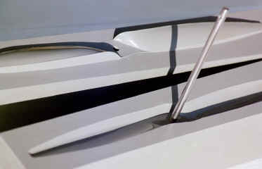

 This picture
shows the carbon tow laid along the leading and trailing edge of the blade in
order to widen the blade. The carbon tow is also filling the damaged void
in the tip. There is excess tow in this area to keep from refilling the
area. It is easier to sand away extra tow than to reapply more carbon tow.
The carbon tow extends well beyond the see temp at the tip and will be trimmed
away with enough material to make the blade longer. These pictures are of
the blade in the finished state before sealing and waxing.
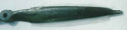
This picture
shows the carbon tow laid along the leading and trailing edge of the blade in
order to widen the blade. The carbon tow is also filling the damaged void
in the tip. There is excess tow in this area to keep from refilling the
area. It is easier to sand away extra tow than to reapply more carbon tow.
The carbon tow extends well beyond the see temp at the tip and will be trimmed
away with enough material to make the blade longer. These pictures are of
the blade in the finished state before sealing and waxing.
